




Capacitors and Filter Caps: Their role in an amplifier
What role do Capacitors and Filter Caps play in an amp's tone? Like the tires and brakes on your car, there are components inside your amp that will wear out with everyday use.
By Dimitris (Bari) Polyzois
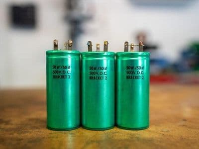
Potentiometers, jacks and switches have a limited lifespan and will eventually need replacing. Unlike your car, though, there's no service schedule for your guitar amp. Something that would make it easy to know when things are likely to go wrong. Without knowing what to look for, it's usually a case of "wait until it breaks." Key components in an amp are the Capacitors.
There are a few components inside your amp that take a real beating and have a very important job. These are called filter capacitors (also known as smoothing caps) and they sit on the high-voltage rail. Their job is to smooth out or filter any ripple in the rectified high voltage that feeds the amp's valves.
There are a few components inside your amp that take a real beating and have a very important job.
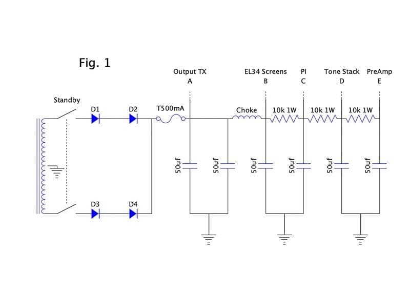
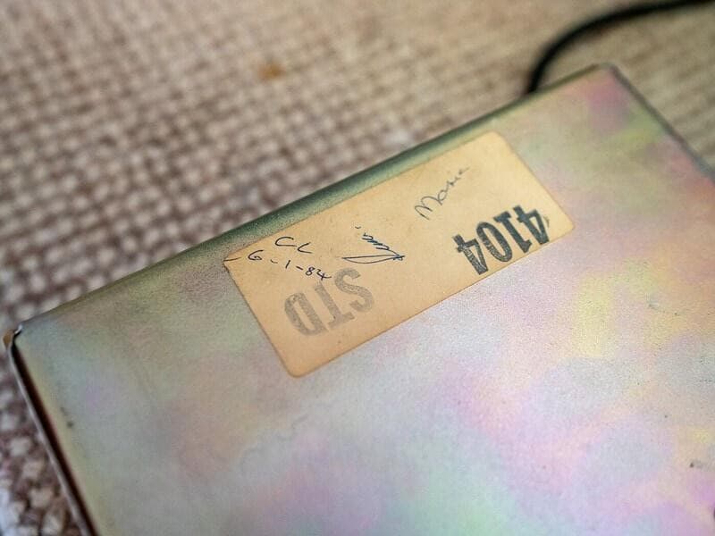
Fig 1 shows the HV rail from a 50w JCM800, model 4104 (the combined version of the 2204). On the left, we have the transformer, the standby switch, the rectifier diodes and the HV fuse. On the right we have six 50uF capacitors – those are the filter caps we're talking about. In this case, they're arranged in three groups of two. That's because, in this amp, the physical caps are packaged exactly that way. The two-in-one format is fairly common and thankfully, the replacement parts are still made today.
Each capacitor or "node" along the rail is given a label, in this case A-E. Each node is where the HV DC is tapped off to feed the various parts of the circuit. I've annotated each node so you can see what's being fed from where.
If we look at node A, we see it feeds the output transformer. The DC is fresh out of the rectifiers at this point, so it needs a fair amount of smoothing and filtering to be usable. The two 50uF Capacitors at this node are connected in parallel, creating a single 100uF capacitor capable of a large amount of smoothing.
This capacitor is also known by another name - the tank capacitor - and its main function is to store most of the entire amp's energy.
Node B sits after the choke and has a single 50uF capacitor. The output valves' screen grids need cleaner DC than the output transformer does, so extra smoothing is required. Then, as we move down the rail towards the final node, E, we see that each stage gets smoothed even further. The preamp section of the amp is the most sensitive to noise, so this stage needs to have the cleanest, least noisy DC.
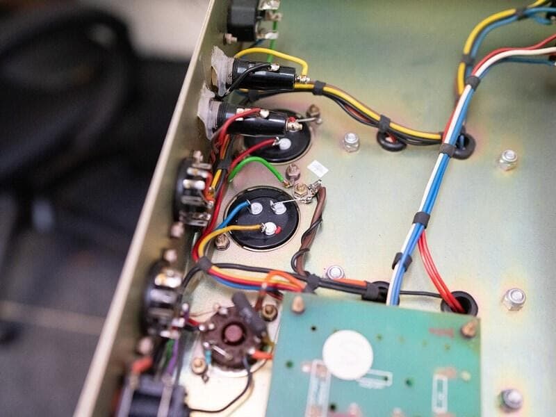
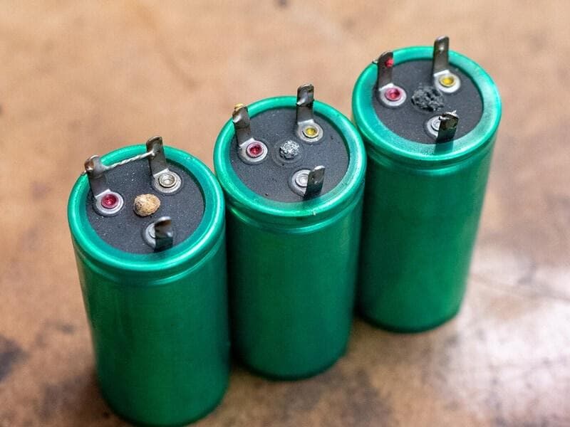
As you can imagine, if any of these capacitors isn't working properly and can't smooth out the ripple. So, the amp will suffer a drop in output. This could be low-level and barely noticeable if the caps are just starting to fail, or it could be so severe that the amp becomes unusable. Very often, a visual inspection of these capacitors can reveal their condition.
The image above shows damaged capacitors. There you can see that each one has burst open at the central relief vent, spraying electrolyte onto the outer casing. If this amp had been regularly inspected by a technician, they would have noticed a bulge forming at that point, indicating that the capacitor was no longer functioning and needed replacing. A capacitor can also be tested electrically, checking both its capacitance and its leakage.
Replacing these Capacitors is fairly easy, though it can be quite time-consuming depending on the number and position of each capacitor inside the chassis. Thankfully, it's not a job that needs doing regularly, with most needing replacement every 10 years or so, depending on use.